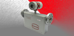
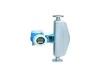
Coriolis Mas Flowmeter


Principle of measurement
In many areas of the industry is more interesting to measure mass flow to volumetric flow. In some processes in the food industry, such as pasta products, pulp or yogurt are often packaged by weight, not volume. For this reason, the labels on the packaging of these products tells the consumer of the product weight rather than volume.
The reason is that the volume of most liquids can vary greatly influenced by the physical conditions of pressure, temperature and density.
By contrast, the mass of a fluid is not affected by these influences - so that the mass flow measurement has some advantages that the volumetric flow simply can not offer. This is an aspect of particular importance in the count of flows for the packaging and billing.
The usual way to determine the mass of a body is weighed. But from the point of view of engineering major difficulties arise when trying to direct a mass despite continuously flowing through a pipeline system. However, in recent decades there has appeared a measurement principle which allows a direct measurement and continuous mass flow in pipes, namely the mass flow measurement by Coriolis principle. In some applications it is more reasonable to apply this principle to determine the mass from indirect methods of measuring volume flow and density (volume x density = mass).
Measuring principle
The first description of this principle is commonly attributed to French mathematician and physicist whose name is known: Gaspard Gustave de Coriolis (1792-1843). The effect only occurs in rotating systems, eg in roundabouts or on rotation of our own planet, but not to be confused with centrifugal force. Although the use of the term "Coriolis force" is widespread, the description of this force is often difficult, and much explanation. This force appears when a system is superimposed in a straight line and rotary motion.
Figure below shows a practical example:
A person still on a rotating circular platform halfway between center and edge simply knock your weight slightly inward to counter the centrifugal force (left). However, if the person moves from center to the edge of the turntable, as it moves seen an increase in speed and the Coriolis force appears as a reaction to the forces of inertia. The Coriolis force tends to deflect the person of the shortest path on the turntable (ie, the straight line on the radius of the circular platform). The higher the speed of the platform, the greater the weight ofthe person and increased your speed to the edge of the circular platform (the "mass flow"), the greater the effect of inertia and the effect will be perceived more Coriolis force.
In mathematical terms, the value of the Coriolis force (Fc) is directly proportional to the moving mass (m), the angular velocity (co) and radial velocity (vr) in the rotating system:
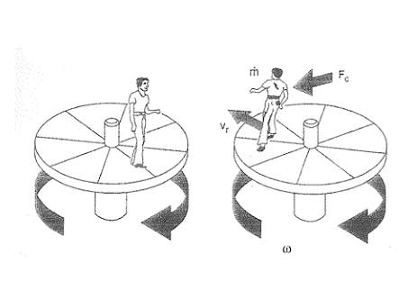
Ill.: Causes and effects of the Coriolis force in a rotating circular platform.
Coriolis forces are always presented in a linear motion system overlap with rotational movements (right). In the absence of linear motion (left, a person at rest), but only perceived centrifugal forces.
vIn a flowmeter Coriolis mass flow, each individual particle mass is subjected to the same influence as the body of the person on the turntable we see in the illustration above (see Figure below). The rotational movement that causes the Coriolis force in the above description in the flow meter is replaced by an oscillating movement of the measuring tube at its resonant frequency.
- A zero flow when the fluid is at rest, there is no linear motion (a). Therefore, there are no Coriolis forces.
- By contrast, when the mass of fluid flows, the movement induced oscillation (equivalent to a rotation) of the measuring tube is superimposed on the linear motion of fluid in circulation, the effects of the Coriolis force "twist" tubes measurement (b, c), and sensors (A, B) at the entrance and exit times show a difference in this movement, ie a phase difference. The larger the mass flow, the greater the phase difference /see Figure A
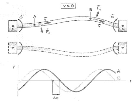
Figure A: Coriolis forces and geometry of the oscillation in the measuring tubes.
When the fluid flows, mass particles move along the measuring tube and are subject to a superimposed lateral acceleration due to the Coriolis force (Fc). At the inlet, particle mass (m) experience a shift away from the center of rotation (Z1), and back again to the center (Z2) as they approach the outlet end. Coriolis forces act in opposite wing entry and exit and the test tube begins a. "Twisted." This change in geometry induced oscillation in the test tube is recorded on the sensors (A, B) at each end of the tube as a phase difference. This phase difference (Δω) is directly proportional to the mass of the fluid and velocity (v) the same, so also the flow máslco.
An important aspect when applying Coriolis flowmeters is the presence of external influences such as vibration of the pipe. Vibration in piping systems often have vibration frequencies between 50 and 150 Hz on the other hand, the resonance frequencies typical Coriolis flowmeters E + H are between 600 and 1,000 Hz, these flowmeters are, therefore immune to vibrations induced in the system of this nature. In addition, for the same reason, these measuring devices require no special mounting vibration inhibitor.
The field values available standard nominal diameters ranging from DN 1 to 300 (1 / 24 to 12 "). However, in practice we can find from dispensing very small amounts in pharmaceutical applications to applications for loading and unloading of ships merchant. The choice of models is correspondingly wide.
Measurement of densities:
The measuring tubes are in constant oscillation frequency of resonance. If the fluid density changes, and therefore the mass of the oscillating system (more fluid measuring tube), the oscillation frequency is adjusted accordingly. The resonant frequency is thus a function of fluid density and can be used as an additional output signal.
Temperature measurement:
The temperature of the measuring tubes is determined to calculate the compensation factor that takes into account the effects of temperature. This signal corresponds to the process temperature and is also available as an output signal.
برای ارسال درخواست ، لطفا اینجا کلیک کنید